

CCS Busbar Lamination: How to Control Bubbles, Bonding and Alignment
Reliable CCS busbar lamination requires a compatible material stack, controlled surface preparation, suitable tooling and a validated bonding process. Increasing temperature or pressure without understanding the defect can create additional problems instead of solving the original one.
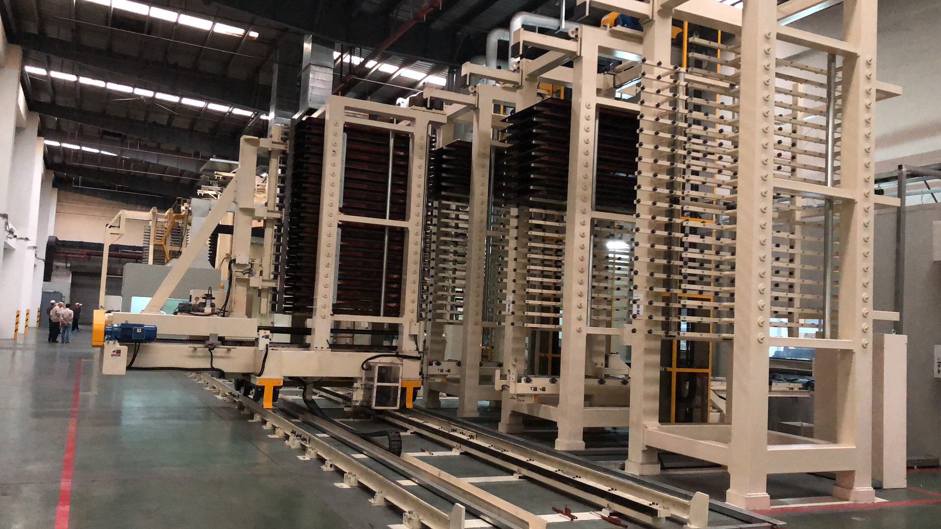
Introduction
Reliable CCS busbar lamination requires a compatible material stack, controlled surface preparation, suitable tooling and a validated bonding process. Increasing temperature or pressure without understanding the defect can create additional problems instead of solving the original one.
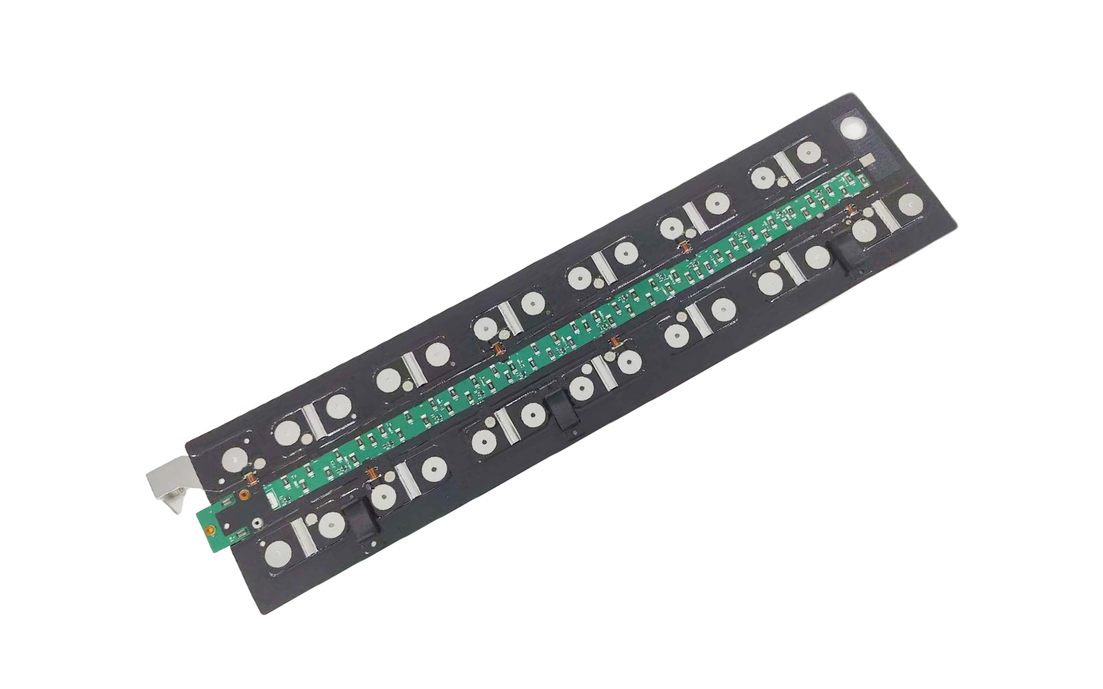
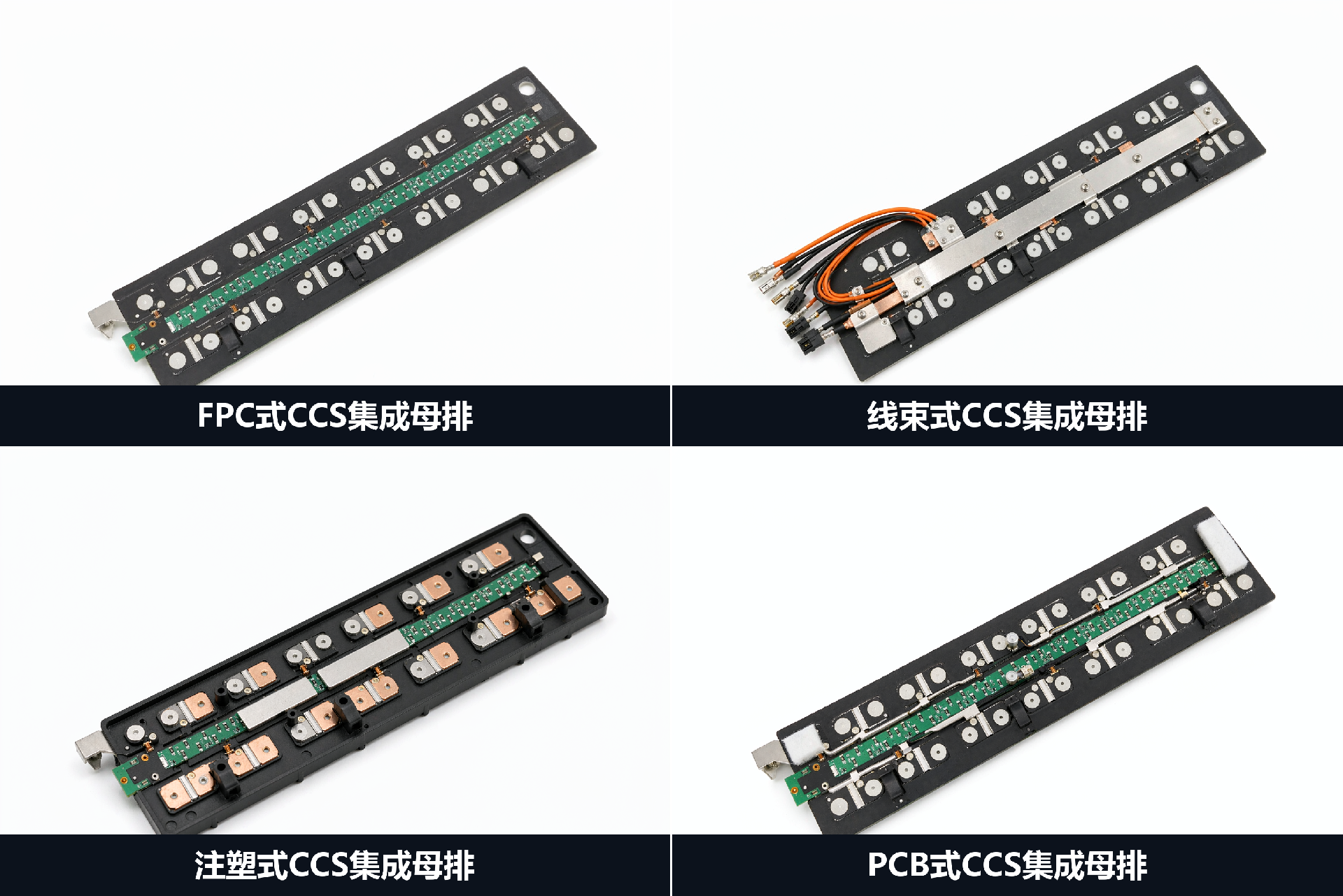
In this article, CCS means cell contacting system. Depending on the design, an assembly may combine conductors, insulation, carriers and sensing-related elements. This discussion focuses on the bonding and insulation-lamination operation; it does not treat lamination as a substitute for welding qualification or complete battery-system validation.
For manufacturers evaluating production equipment, the main question is practical: can the proposed process produce assemblies that consistently meet dimensional, bonding and electrical requirements?
Answering that question involves more than observing a clean-looking sample. Buyers need to understand which variables affect quality, how defects will be investigated and what factory testing should demonstrate.
The following framework connects common lamination concerns with measurable process and equipment requirements.
Confirm the Bonding Method First
Not every CCS insulation assembly requires the same bonding process.
Some constructions use heat-activated adhesives or bonding films. Others use pressure-sensitive adhesive systems with different processing requirements. Materials marketed for battery applications should not automatically be treated as suitable for a particular hot-press cycle.
Avery Dennison’s EV battery portfolio includes pressure-sensitive adhesive solutions for insulating cell connect systems and busbars. This is a useful reminder that the adhesive technology must be identified before selecting equipment or temperature settings.Avery Dennison EV battery solutions
Ask the material supplier to confirm the bonding mechanism, compatible surfaces and processing instructions.
If heating is required, establish whether it activates bonding, supports flow or contributes to a curing reaction. If pressure-sensitive bonding is used, confirm the specified application pressure, surface preparation and any conditioning period.
The equipment discussion should follow that verified material route.
Describe the Full Material Stack
A statement such as “copper busbar with insulation film” leaves too many variables unresolved.
Document the conductor material, thickness, surface finish, insulation designation, adhesive grade and relevant protective layers. Include local thickness changes, openings and areas that must remain unbonded.
Identify release liners clearly. An incorrect assumption about which liner is removed, or at which stage, can invalidate an otherwise sensible trial.
Also define finished-part requirements: insulation overlap, feature position, permissible adhesive squeeze-out, flatness and thickness.
Busbar manufacturers use a range of dielectric materials and application-specific laminating arrangements. Material selection and processing therefore need to be considered together.Mersen busbar manufacturing information
Before equipment selection, prepare a controlled stack drawing and bill of materials. Give each revision an identifier so test results remain associated with the construction actually evaluated.
Without that traceability, a later material change can appear to be a machine problem.
Turn “Good Lamination” into Measurable Requirements
A visually smooth surface is useful evidence, but it does not establish complete assembly quality.
Separate requirements into dimensions, bonding, electrical performance and durability.
Dimensional requirements may include conductor location, insulation coverage, thickness and flatness. Bonding requirements need a defined test method and sample preparation procedure.
Electrical requirements should come from the customer’s component specification and applicable design requirements. Do not derive a universal test voltage from the press model or insulation-film description.
Where durability matters, agree the relevant conditioning or environmental exposure before evaluating retained performance.
The acceptance plan should state who performs each test, which samples are used and how failures are handled.
Avoid vague criteria such as “no obvious defects” unless the inspection conditions are also defined. Lighting, viewing distance, magnification and defect size can change whether two inspectors reach the same conclusion.
A measurable specification makes supplier trials more useful and prevents disagreements after delivery.
Investigate Bubbles Through Several Possible Mechanisms
Bubbles or blisters can arise from different causes, so appearance alone should not determine the corrective action.
Possible contributors include trapped air, moisture, contamination, volatile release or incomplete contact. Their likelihood depends on the adhesive, insulation and production sequence.
Begin by mapping the defect location. Does it appear near an edge, around a conductor step or randomly across the surface? Does it occur immediately or develop after cooling or conditioning?
Check material storage and handling records. Review liner removal, lay-up order and the time between preparation and pressing.
For heat-assisted bonding, compare the actual interface temperature with the intended process window. Excessive heating can be as problematic as insufficient heating for some constructions.
Change variables through a controlled trial plan. Increasing heat, load and dwell simultaneously may improve one sample while leaving the true cause unknown.
Treat the result as a testable explanation until repeated evidence supports it.
Control Preparation, Cleanliness and Edge Condition
Surface preparation needs a defined procedure compatible with the conductor finish and adhesive.
Specify the approved cleaning method, handling sequence and contamination controls. Do not assume that a stronger solvent is always more effective or compatible.
Check whether preparation leaves residue or damages a coating. Where cleaning is required, confirm that the surface is ready for bonding before assembly.
Inspect conductor edges and local features. Burrs or sharp projections can affect contact and may damage thin insulation during pressing or later handling.
Use suitable fixtures and protective handling methods to preserve prepared surfaces. Parts should not be returned to uncontrolled benches after cleaning.
For troubleshooting, keep samples and records from both acceptable and rejected runs. Comparing the actual surfaces and preparation history may reveal differences that are invisible in a list of machine setpoints.
Preparation should be part of the production specification, with responsibility assigned clearly between the component supplier and the lamination operation.
Measure Temperature Where Bonding Happens
The platen setpoint is not necessarily the adhesive-interface temperature.
Conductors, fixtures and insulation layers create different thermal paths. Local metal mass and tooling contact can affect heating behavior across an assembly.
During process development, use a representative setup to understand critical temperatures. Identify measurement locations and consider whether the sensor itself changes the contact condition.
Define when dwell time begins. A timer started when the press closes may provide a different effective bonding period from one started after the relevant location reaches the required temperature.
Also review temperature overshoot and differences between upper and lower surfaces.
For a multi-opening machine, evaluate representative positions rather than assuming one measurement represents every opening.
The goal is to establish a relationship between the machine recipe and the material conditions that matter. Once that relationship is understood, production monitoring can be designed around the approved process.
Avoid publishing a generic temperature range as though it applies to every CCS adhesive system.
Specify Pressure, Contact and Alignment Together
Pressure must refer to a defined area
Hydraulic circuit pressure, total closing force and pressure on the stack are different quantities.
Ask the supplier to explain how the machine’s readings relate to the actual tooling arrangement. Steps, cutouts, spacers and hard stops can change where load is carried.
If stops control final thickness, additional force may be transmitted through them rather than producing the assumed increase in adhesive pressure.
Excessive load may also create squeeze-out, distortion or damage in susceptible constructions. The suitable range must come from material guidance and representative trials.
Alignment depends on tooling and handling
Review locating pins, nests, datum features and the way films are positioned before closing.
Check whether the assembly can shift while loading or during early press contact. Consider differential movement during heating and cooling.
A useful trial evaluates alignment after the full process, including unloading. Correct location before pressing does not prove that the finished assembly will remain within tolerance.
Planning a CCS lamination process?
Send KLT your stack drawing, adhesive instructions, finished-part dimensions and current quality concerns. Include photographs or inspection records that show where defects occur.
Decide Whether Vacuum Adds Value
Vacuum can help some lamination processes remove air, but the equipment must provide a workable evacuation path.
A low chamber-pressure reading does not prove that air has escaped from every interface. Contact may seal an area before trapped air can leave.
Discuss the sequence of evacuation, heating and force application. Confirm whether the tooling, material geometry and sealing arrangement support the intended sequence.
Where vacuum is proposed, define how its performance will be assessed under representative conditions. Consider leakage, measurement location and the behavior of the actual loaded assembly.
Compare otherwise controlled trials where appropriate. Evaluate the resulting parts rather than selecting vacuum solely because it appears on an equipment specification.
If the root cause is contamination, unsuitable adhesive or a damaged film, vacuum may not address it.
The purchasing decision should identify which problem vacuum is expected to solve and what evidence will show that it has done so.
Planning a CCS Busbar Lamination Project?
Tell us about your material stack, assembly size and production target. Include your current bonding or alignment concern.
Request a CCS Project ReviewEvaluate Multi-Opening Capacity Using Quality and Workflow
Multi-opening equipment can support batch production, but nominal opening count is only one capacity input.
Review loading time, fixture availability, material preparation and operator access. Confirm whether all openings will be used for every product.
Map temperature behavior and quality across representative positions. Different tooling masses or loading patterns may affect the process.
Ask how the machine transmits force through the proposed stack arrangement. A common load path differs from independently actuated stations, and neither should be evaluated through opening count alone.
Calculate good assemblies per hour using complete cycle time, utilization and first-pass yield.
For example, a machine producing more assemblies per cycle may deliver fewer accepted parts if loading is difficult or defects increase at certain positions.
Also assess changeovers. A configuration that performs well with one stable product can be less suitable when the factory regularly changes assembly size or stack construction.
Request a demonstration that reflects the intended product mix.
Use a Structured Defect Review
The following table supports investigation. It identifies possible mechanisms and checks rather than diagnosing a defect from appearance alone.
| Observation | Possible contributors | Useful checks |
|---|---|---|
| Bubbles after pressing | Trapped air, moisture, volatiles, incomplete contact | Storage records, evacuation sequence, interface temperature |
| Edge lifting | Surface condition, contact loss, adhesive incompatibility, cooling stress | Preparation method, edge geometry, bonding instructions |
| Wrinkles | Lay-up tension, positioning, material movement | Loading method, fixtures, sequence of first contact |
| Excess squeeze-out | Adhesive amount, temperature, force, thickness control | Stack dimensions, actual thermal history, tooling stops |
| Local insulation damage | Burrs, particles, excessive local contact | Edge inspection, cleanliness, fixture condition |
| Misalignment | Insufficient location, handling movement, thermal movement | Datums, nests, loading and unloading steps |
Record where and how frequently each defect occurs.
An isolated edge defect may require a different investigation from a consistent pattern associated with one opening or one material batch.
Build Factory Testing Around Representative Assemblies
A meaningful factory test starts with agreed samples and criteria.
Use the intended conductor finish, insulation, adhesive and tooling where practical. If a substitute is used, state which aspects of the process it can represent.
Define the run sequence, inspection sample and records required before testing begins. Include enough repetition to evaluate the agreed production conditions rather than selecting only the best-looking assembly.
Capture material batches, stack revision, recipe, equipment settings, relevant measured temperatures and inspection results.
Where multiple openings are used, retain the position identity of each sample. This helps reveal patterns that disappear when all results are pooled.
Include a controlled approach to adjustments. Record what changed, why it changed and which samples belong to the revised settings.
The resulting report should allow a quality engineer who was not present to understand the test and evaluate the evidence.
Separate Visual, Bonding and Electrical Verification
These inspections answer different questions.
Visual inspection assesses observable defects and coverage. Dimensional inspection checks geometry. Bonding tests examine a defined response of the joint.
Electrical testing assesses specified insulation characteristics under defined conditions. A visually acceptable assembly should not automatically be treated as electrically acceptable.
Research on laminated busbars also distinguishes insulation-design considerations and partial-discharge behavior. However, findings for one busbar construction should not be transferred directly to every CCS assembly.Research on laminated busbar insulation systems
Where dielectric withstand, insulation resistance or partial-discharge testing is required, obtain the method and acceptance limits from the responsible customer or design authority.
Define test connections, conditioning, equipment and operator competence. These details affect whether the result is meaningful.
The press supplier’s role and the component manufacturer’s qualification responsibilities should be recorded separately.
Prepare the RFQ and Installation Plan
Give equipment suppliers enough information to review the application:
- Controlled stack drawing and material designations.
- Adhesive processing instructions.
- Part and fixture dimensions.
- Required dimensional, bonding and electrical outcomes.
- Production target and product mix.
- Traceability and data requirements.
- Factory-test scope.
- Installation country and site utilities.
If the process window is unknown, request a defined development or trial stage instead of treating unverified settings as final specifications.
For installation preparation, review clean handling space, cooling utilities, loading access and inspection flow. Include safe storage for materials and finished assemblies.
Define shipment inspection separately from process approval. The shipping check should confirm machine identity, accessories, documents, packing condition and completion of agreed corrective work.
These preparations help ensure that a successful trial can be reproduced after installation.
FAQ
What temperature should be used for CCS busbar lamination?
Use the adhesive or bonding-material supplier’s instructions and validate them on the actual stack. There is no universal temperature for every CCS construction.
What causes bubbles in busbar insulation lamination?
Possible causes include trapped air, moisture, contamination, volatile release and incomplete contact. Defect location, timing and controlled trials help distinguish them.
Does higher pressure improve bonding?
Only within a suitable process window. Excessive load may create squeeze-out, distortion or local damage. Evaluate pressure together with temperature, tooling and adhesive behavior.
Is vacuum necessary for CCS lamination?
Not always. Its value depends on the materials, geometry and evacuation path. A representative trial should establish whether it improves the required outcomes.
How should a multi-opening press be evaluated?
Check complete output, opening utilization, loading effort and quality by position. Confirm the force path and thermal behavior for the proposed arrangement.
Can visual inspection confirm electrical insulation quality?
No. Visual inspection and electrical verification serve different purposes. Perform the tests required by the component specification.
Conclusion
CCS busbar lamination quality depends on the complete material-and-process system.
Start by confirming the adhesive technology and controlled stack design. Then connect surface preparation, temperature, force, air removal and alignment to measurable product requirements.
A strong equipment proposal explains how those conditions will be achieved and how representative assemblies will be tested. This creates a more reliable basis for purchasing than machine size or cycle speed alone.
Discuss Your CCS Lamination Requirements
KLT provides hot-press equipment for CCS busbar lamination projects. Share your assembly drawing, insulation and adhesive information, production target and inspection requirements to discuss a suitable equipment scope.
Continue your equipment review
Planning a CCS Busbar Lamination Project?
Tell us about your material stack, assembly size and production target. Include your current bonding or alignment concern.
